10 Results
View results:
Sort by:
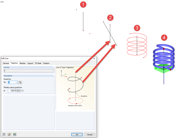
In RFEM, you can create screw lines using the "Trajectory" type line. To do this, you need a center line/guide line around which the line can be modeled, as well as a start and end point. Then, you can create a "Trajectory" type line between the start and end points; this initially appears as a straight line.
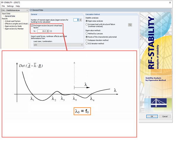
The function, which is also known as shifting, allows you to calculate critical load factors beyond a user‑defined initial value. Determination of the critical load factors is usually done from the smallest to the greatest critical load factor.
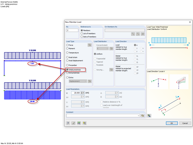
Until now, the prestress load type had always been an initial prestress in Dlubal Software programs. The defined load magnitude was applied and, depending on the stiffness of the surrounding system, prestress remained more or less as an axial force in the cable.
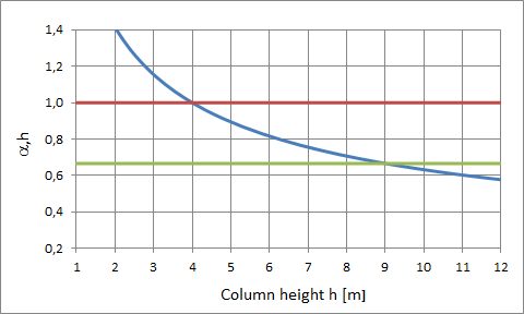
According to EN 1993-1-1 [1], it is necessary to use the equivalent geometric imperfections with values that reflect the possible effects of all types of imperfections. EN 1993-1-1, Section 5.3, specifies basic imperfections for the global analysis of frames as well as member imperfections.
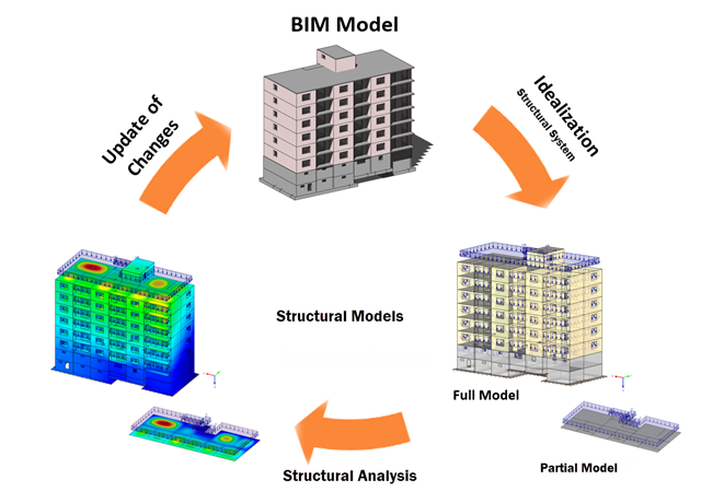
Building Information Modeling describes what is possibly one of the most important current topics in the entire construction software industry. However, the process is not that new, and it is a well-known fact that the total costs of a project can be positively influenced by good planning in the initial stage.
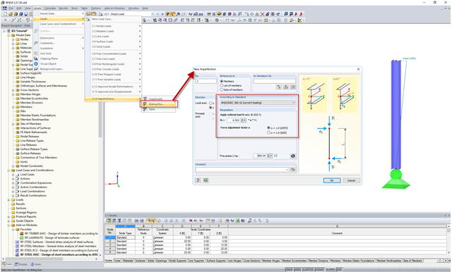
In the AISC 360 – 14th Ed. C2.2, the direct analysis method requires initial imperfections to be taken into consideration. The important imperfection of recognition is column out-of-plumbness. According to C2.2a, the direct modeling of imperfections is one method to account for the effect of initial imperfections. However, in many situations, the expected displacements may not be known or easily predicted.
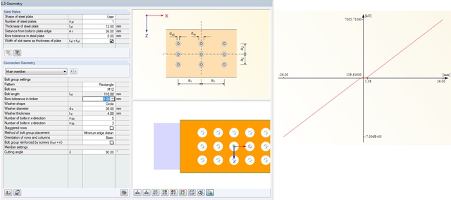
In RF-JOINTS Timber – Steel to Timber, you can consider the possible minimum slippage of bolts in the case of guide pins. In RFEM, this slippage is taken into account using the flexibility in member end releases.
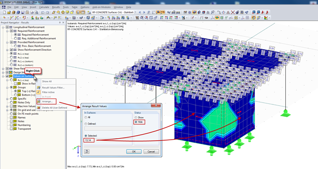
In RFEM, you can display the result values of surfaces (from RF‑CONCRETE Surfaces, for example), which can specify the required reinforcement of the designed surfaces in grid points. Generally, the result values are initially displayed for all surfaces designed.
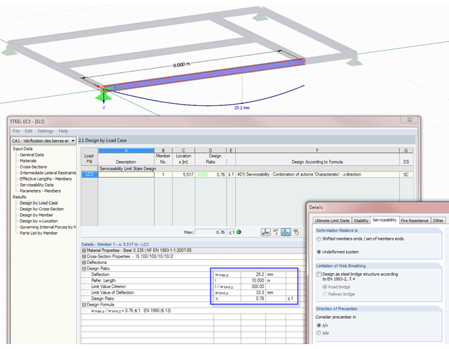
Not only do RF-/STEEL EC3 and RF-/TIMBER Pro perform cross-section designs and stability analyses, they allow you to perform serviceability limit state designs. For this, it is possible to relate the deformation to the undeformed initial system or to shifted members ends.
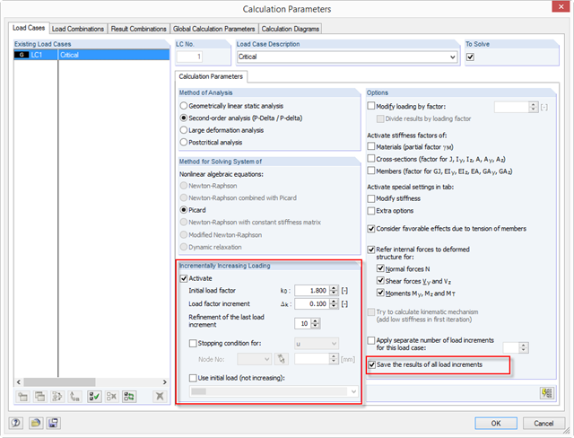
With RFEM 5.04, there are new options for the system analysis (critical load factors) of load cases and load combinations in the calculation parameters of the RF‑STABILITY add‑on module: ~ The load increment is not closed due to stability problems, but optionally also due to predetermined deformation limits. ~ The calculation method is applicable to all nonlinear calculations. ~ You can define an initial load (LC/CO) that is not increased (for example, self-weight). ~ The "Refinement of the last load increment" option provides an efficient option to determine the critical load factor as precisely as possible.